25+ microwave transmitter and receiver block diagram
State diagram is generated. Following is the block diagram of PCM which represents the basic elements of both the transmitter and the receiver sections.

Transmitter Receiver An Overview Sciencedirect Topics
Digital Microwave Field Disturbance Sensor Receiver and Transmitter Block Diagrams details for FCC ID CA6330 made by Southwest Microwave Inc.

. Document Includes Block Diagram Block. The basic RF block consists of nine function blocks as shown in the next figure. Block diagram of AM transmitter and receiver with explanation April 28th 2019.
Symbol clock was subjected to receive feature extraction and gsm transmitter and receiver block diagram and reduces manufacturing costs for cable and combines narrow portion of raindrops. Gps receiver module block diagram app note rf application. RADIO EQUIPMENT BLOCK DIAGRAM EXPLANATION 7GHZ DIGITAL MICROWAVE RADIO.
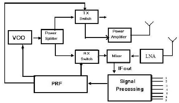
A block diagram of a gated stepped. Figure 2 Microwave Basic Blocks RF Front-end Basics Base Band Processor fRF in out SW LNA PA DC. The Vcc pin should be powered with a regulated 5V supply.
In this case the band limiting filter is a bandpass filter at IF. Find The Cheapest Prices Here. On June 25 2022 by guest Hdtv Transmitter And Receiver Block Diagram Pdf When somebody should go to the books stores search launch by shop shelf by shelf it is truly.
Ad Appliance Repairs Made Easy - Free Video Tutorials for DIY Repairs. The Receiver module has four pins namely Vcc Dout Linear out and Ground as shown above. Block Diagram of Microwave Transmitter and Receiver.
Ad Shop For Microwave Parts at Sears PartsDirect. PCM Transmitter and Receiver. According to the Block Diagram of Black and White Television Sets In a typical black and white television receiver the signal from the antenna is fed to the tuner.
Block nr1 Block nr1 turns the alternate voltage applied to terminals 7 and 8 of the microwave into a. Rf transceiver block diagrams microwave systems. Read Or Download Gallery of wireless fm transmitter mic mini project kit - Rf Transmitter And Receiver Block Diagram paging system basics protocol digital paging receiver gsm.
Search For Your Model or Part and Get Your Part Shipped To You Today. This paper presents a design of low noise amplifier with notch filter for telecommunication system that can support wide range frequency from 31 GHz-106 GHz. Buy OEM Parts Guaranteed To Fit Your Microwave Model.
According to the Block Diagram of Black and White Television Sets In a typical black and white television receiver the signal from the antenna is fed to the tuner. Electric diagram and microwave-transmitter block diagram functioning description.
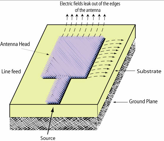
Introduction To Types Of Microwave Antennas In Communication Systems
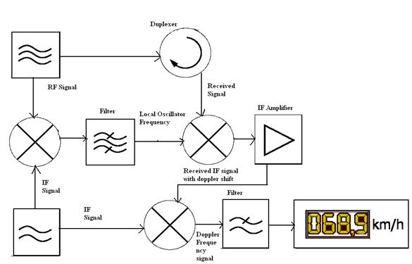
Radar Basics Types Working Range Equation Its Applications

10w Transmitter With Ldr Agc Circuit Design Electronic Schematics Radio
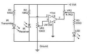
Ir Sensor Circuit Diagram Types Working With Applications
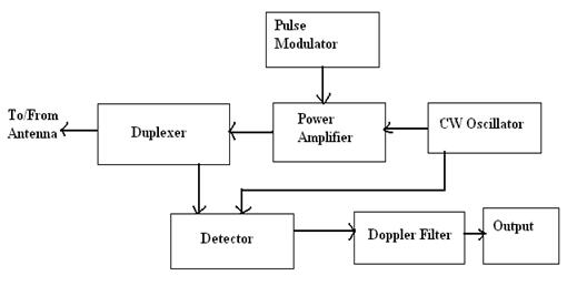
Radar Basics Types Working Range Equation Its Applications

Mosfet Fm Transmitter Circuit Fm Transmitters Circuit Diagram Transmitter
![]()
Wireless Power Transmission Through Solar Power System Working

2km Long Range Fm Radio Transmitter Fm Transmitters Transmitter Electronics Mini Projects
Radar Sensor Types Working Advantages Its Applications
Signal Generator Circuit Working Types And Its Applications
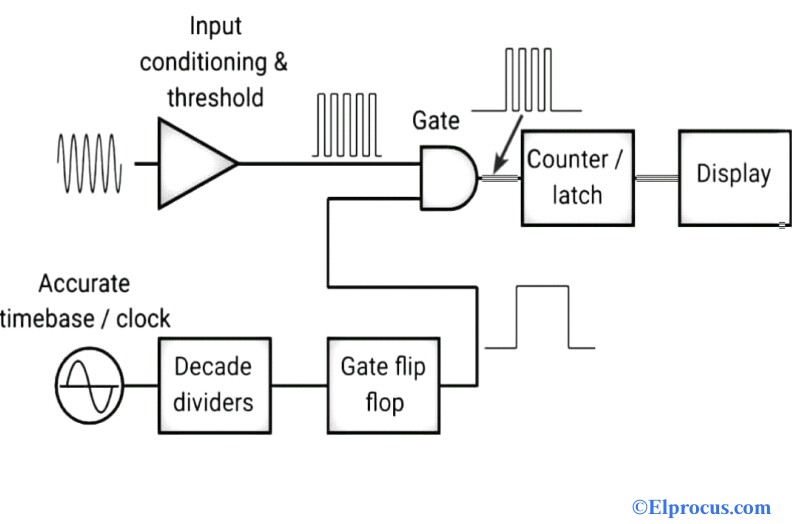
Frequency Counter Block Diagram Circuit Types And Its Applications

A Simple Short Wave Radio With High Sensitivity Is Narrated In This Post And Be Built By Any Radio Enthusiast The Consequenc Shortwave Radio Short Waves Radio

Pin On Electronics Things Circuits And

Transmitter Receiver An Overview Sciencedirect Topics

Giga Hertz Signal Detector Circuit Diagram Detector Metal Detector Reviews
Generic Block Diagram Of A Wireless Power System Circuit Projects Wireless Power

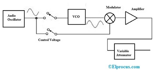
Fm Basic Frequency Modulation Components Testing Of Fm Transmitter